Class 5: Modelling with UML diagrams#
UML diagrams are used to illustrate broadly understood systems, such as architectures, state dynamics or workflows. There are many tools to draw them: those into graphic design may like drawing tools like diagrams.net, while developers should appreciate diagrams created from markup descriptions by PlantUML or by more simplistic Mermaid. It is worth looking into examples shared online, see in particular https://real-world-plantuml.com/ or https://www.planttext.com/. For more on UML modelling, see dedicated courses like here or here.
Example: Content Summarizing App#
Business requirements are best illustrated with (high-level) use-case diagram, which visualize how actors interract with a system to accomplish some actions. Note that actors can be computer systems or services as well as human users.
Note
A good use-case describes a situation bringing added value. Some events don’t have enough impact to be good use-cases, see this discussion on user logging.
The example below visualizes a we application which visualizes/summarizes extracted content to its users. Note that, in this case, daily data update is considered an added value inedendent of visualization.
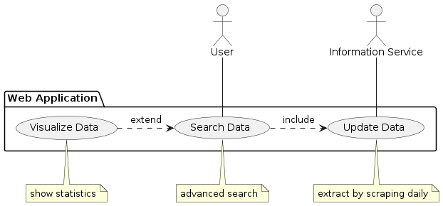
This was generated with the following PlantUML code snippet:
@startuml

actor "User" as user
actor "Information Service" as web
package "Web Application" as webapp {
    usecase "Search Data" as UC1
    usecase "Visualize Data" as UC2
    usecase "Update Data" as UC3
}

user -- UC1
web -- UC3
note bottom of UC3: extract by scraping daily
note bottom of UC2: show statistics
note bottom of UC1: advanced search

UC1 .> UC3: include
UC2 .> UC1: extend

@enduml
Example: GitHub Game#
As an exmple, let’s model an educational game which challenges users with questions about coding practices based on Github repositories.
To this end, we create the following sequence diagram showing interaction steps (test it live here):
The corresponding PlantUML code snippet is
@startuml
autonumber

actor User as user
participant "Application" as app
participant "GitHub" as github

skinparam actorStyle awesome

loop until user ends
    user -> app: challenge request
    app -> github: sample a repo
    github -> app: return the repo information
    app -> user: puzzle
    note left of app: question about filetypes/locations
    user -> app: answer
    app -> user: evaluation
end
@enduml
A very similar diagram is created by Mermaid, with slightly different syntax (test it live here).
sequenceDiagram
    autonumber

    actor user as User
    participant app as Application
    participant github as GitHub

    loop until user ends
        user ->> app: challenge request
        app ->> github: sample a repo
        github ->> app: return the repo information
        app ->> user: puzzle
        note left of app: question about filetypes/locations
        user ->> app: answer
        app ->> user: evaluation
    end
Example: Web App by Model-View-Controller#
The example below illustrates the application of the Model-View-Controller framework which separates interface and business logic. To do so, it uses elements with distinguished roles - such as boundary, control or entity objects, called stereotypes. The system depicted is a web application which visualizes data scrapped on a daily basis from web resources.
The code snipppet is shown below
@startuml

actor User as user
boundary Dashboard as view
control Logic as logic
entity Database as db
control Scrapper as scrape
entity WebSources as web

skinparam actorStyle awesome

activate db
activate view

loop daily
    scrape -> web: get
    activate scrape
    web --> scrape: page
    scrape -> scrape: process
    note right of scrape: parsing
    scrape --> db: upload data
    deactivate scrape
end

user -> view: information request
activate user
view -> logic: pass request
activate logic
logic -> db: read
db --> logic:  data
logic -> logic: process
note right of logic: computation
logic --> view: response
deactivate logic
view -> user: update
note left of view: notify/refresh
deactivate user

@enduml
and renders as follows